89 KDX200 Headlight. Help & win a cookie...seriously.


DirtyRyan

Member
Jul 29, 2009
63
0
Hey ya'll,
So I'm sitting here looking at this headlight:
http://www.motorcycle-superstore.com/2/9/195/7297/ITEM/Acerbis-CE-DOT-Certified-DHH-Headlight.aspx

Which is sitting next to this 3way toggle switch:

http://www.motosportsfactory.com/es...duct_607788.PROGRESSIVE_SUSPENSION_UNIVER.htm

Which, are both sitting next to this bike:

1989 KDX200 E: http://justkdx.dirtrider.net/images/91kdx250.jpg


My question....now what? If you can provide me with some dumbed down, step by step help here that results in a working headlight with high, and low beam...then I will promptly send you some of my girlfriends amazing baked goods. Unless of course you don't want baked goods, in which case I will give you a hearty "e-handshake & thank you". Your choice. Thanks.
 

julien_d

Member
Oct 28, 2008
1,788
0
So I guess the original headlight and switch are missing? Is the voltage regulator in place? How about the original wiring harness for the headlight and switch? If that stuff is still on the bike, it should be a pretty easy install. If not, you will need this....


julien_d

Member
Oct 28, 2008
1,788
0
So the headlight ran right off the magneto? I did not know for sure. The lighting harness had been gutted from my 89 when I got it, but all the parts diagrams I have looked at for my bike clearly show a VR. How did that work without totally sucking? Wouldn't it be best to score a VR from a 90 and wire it in? I just now noticed the VR missing from the service manual for my bike. I haven't needed to do much with the wiring before, so I hadn't paid too much attention to the wiring schematic in my manual.

I guess that could simplify things a bit?
 

dirt bike dave

Sponsoring Member
May 3, 2000
5,349
3
The problem with no voltage regulator on the '89 is you are more prone to blowing out bulbs. Since most guys turn their headlights off in the daytime, the tail light bulb is the one that blows out most often.
 

DirtyRyan

Member
Jul 29, 2009
63
0
Diagrams Hooray!

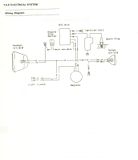
Ok, to make this easy, I went ahead and took the same diagram you provided, then made the appropriate changes as needed to reflect the way it is presently set up, and, in the second image, to detail through diagram, where I encounter the "?'s".

So the present set up is very similar to what you posted.
This diagram reflects the differences between your diagram, and how mine is presently connected. The only changes in mine, are:

1. No headlight hooked up
2. No Taillight hooked up
3. No Light switch hooked up
Here's how it is presently with those changes:
http://i102.photobucket.com/albums/m118/OlyRyan/Picture5-4.png

Now then, after taking a look at that and considering the first diagram you presented, take a look at the following one. It shows you basically the parts that I picked up that have me scratching my head over here.
http://i102.photobucket.com/albums/m118/OlyRyan/Picture2-8.png
Notice there are 3 connection spots on BOTH headlight bulbs (high/low), compared to the hook ups which are set for the old school single bulb.
Additionally, notice that the switch is a 3way toggle. One set for High, One for Low, and one for Off (at least I would think that'd be correct anyway).
Also, at present, all those lines in the second image just represent little terminals/hookups. There is no actual wiring connected to any of those parts yet.

So then, anyone as confused as me or does someone actually know what to do with this?
 
Last edited:

SS109

Member
Jul 27, 2009
310
0
I will assume that the switch is a SPDT type. If you don't want the 4 watt running light then this will work. If you must have the running light then just attach the positive to the "low" beam relay via the #87 terminal and all should be well.

The reason for using the relays is to isolate the tail light. If you don't, the electrical current will try to flow to the "high" beam via the tail light circuit.

Hope this helps!

Image removed as I made an error.

BTW, this is what a relay should basically look like.

bosch_relay02.jpg
 
Last edited:

DirtyRyan

Member
Jul 29, 2009
63
0
SS109:

Would that provide a highbeam and lowbeam though? Cause when I go down to get all the paperwork and other legal nonsense taken care of, they're gonna at some point, want to make sure it passes all the basic requirements, including switching the light between high beam and low beam. I mean, if so, cool...I just have to ask though cause me with electrical wiring is like a monkey with a math problem
 

dirt bike dave

Sponsoring Member
May 3, 2000
5,349
3
Oh, so you are trying to make the bike street legal. I thought you just wanted to get a working headlight.

What state are you in? State requirements vary dramatically, and in many cases it involves much more than just a DOT approved headlight. Some states require a battery and turn signals, for example.
 

DirtyRyan

Member
Jul 29, 2009
63
0
Ya know, I probably should have mentioned that at the start of this post, haha. Sorry about that. Yeah, I'm in Texas so the requirements are pretty bare bones thank god. If I'm not mistaken, all they need is:
1.Headlight w/ working High/Low beam
2. Horn
3. 1 Mirror
4. Tail light
5. Brake Light
6. License Plate Light

Other than that they're pretty relaxed.

So now that we've got that much clarified...

Anyone know how the heck to rig this wiring up?
 

SS109

Member
Jul 27, 2009
310
0
Please disregard the diagram I made as there is an error in it. (Thats what I get for trying to think when I was tired) Give me a few and I will have it for you and yes, it would be a high/low setup.
 

sr5bidder

Member
Oct 27, 2008
1,463
0
parts unlimited cat. no. 2112-0090 moose racing Volt Pack 12v regulator

your voltage will still be ac though and might not run your horn and you may need a rectifier for the wire going to the horn.

from what i see there in the diagram you will need to take the red to the switch common then two more wires one for high and one for low beam leads on the switch to the light hi and low

the blk/ylw wire goes directly to the headlights ground tab and Does not go near the switch. you can then run an additional wire off the center or common of the headight switch through the crossbar pad on the handlebars into a momentary switch on the left side bars out of that switch down the bars and to the left radiator shroud then into a rectifier -out of the rectifier to the horn + side then some horns have a negitive tab other have a wire that is staked on to the body of the horn ..either way you need to take that back to the frame and ground it ..preferably where the rectifier is grounded or the blk/ylw is grounded

ps the switch should NOT have an off position for the head light they might fail you motorcycles run the head light at alll times.

the kdx is kida cool in having a bracket for a brake light switch though it is a long way from the lever i'm sure you can figuer out how to mount a spring to the lever and the switch.... from the switch you would have an input (the red wire) and an output ,,,the out put gets wireed into the second terminal on two filiment buld housings where the first terminal gets the red wire directly for the running light in the rear again the outside of the bulb fixture should have a black wire soldered to it this would go to the blk/ylw wire.. the liceinse bulb would come off the terminal 1 of the tailight and also to ground (if your liceinse light and running light are not the same light as most enduro's are)

normally the horn the tail light and the turning signals get their power from the rectifier/regulator and the headlight runs on the ac currant directly.

yes by the way, parts unlimited carries a regulator/rectifer combo for 12-20 bucks I forget the price and part #
 

SS109

Member
Jul 27, 2009
310
0
I would add a regulator as sr5bidder has suggested. It should be pretty easy to wire that in to the current wiring. If you need help when you get to it just let me know and I'll draw it up for you.

OK, let's try this again. For wiring up high/low beam headlights with what you have this is how I would wire it. The diodes and relays isolate the individual circuits for high and low. If not, one would always feed the other and both circuits would be on whether you had it set to the high or low beam position. Don't forget that you are going to need a high output stator. When the high beam is activated you will have two 35 watts filaments running plus the tail/brake light.

KDXwiringforAcerbisHDDlightrevised.jpg
 

SS109

Member
Jul 27, 2009
310
0
It really isn't that bad. It just looks like it! BTW, the regulator should add in easily. However, the regulator by itself will not give you a high/ low beam setup.

EDIT: I forgot to add that you could wire the running light on to either the low or high beam relay on the 87A pin. If you do this it will be on when your low or high beam headlight is off.

Curious, how come you didn't go with the FRP setup or did you just want a different headlight?
 
Last edited:

reepicheep

Member
Apr 3, 2009
670
2
Do you know how much current that three way switch can handle?

If you are willing to go without regulation, then it seems like you could just tap into the line going to your tail light (or any other hot line), hook that to the center pole of your 3 way switch, then run one other pole to the high beam lead on the headlight, the last pole to the low beam of the headlight, then just ground the other ends of the headlight bulb(s).

If there is an obvious reason not to do this? Is that 3 way switch unable to handle the 5 amps or so for the headlight?

If nobody posts some obvious flaw in my thinking, I'll put together a simple schematic for the 4 connections...
 

SS109

Member
Jul 27, 2009
310
0
He doesn't have a high and low beam. Each filament is 35 watts. Unless somehow one 35 watt filament is brighter than the other you would need both filaments running to have a high beam. Am I incorrect?
 

reepicheep

Member
Apr 3, 2009
670
2
Ahh. So a diode would have to be added...

ground --- filiment --o--- high beam pole
............................|...............................\
............................V (diode).....................switch -- V+
............................-.............................../
............................|...............................
ground --- filiment --o--- low beam pole


So high beam position lights both lights, low beam position lights one.

Thats 70 watts through that switch though, about 6 amps. You would want to make sure the switch can handle that. If not, you are stuck with the relays.

(actually, if you were willing to live with either low or high beam, and never switch both off, you could do it with one relay)...
 

SS109

Member
Jul 27, 2009
310
0
reepicheep said:
So high beam position lights both lights, low beam position lights one.

Thats 70 watts through that switch though, about 6 amps. You would want to make sure the switch can handle that. If not, you are stuck with the relays.

(actually, if you were willing to live with either low or high beam, and never switch both off, you could do it with one relay)...
Yeah, that switch is the big question. I tried finding the specs on it but came up with nothing. Being that I couldn't find them I figured a relay setup would be the safest.

BTW, here is a link to a relay available at Radio Shack stores that will work. Crimestopper XX-402A High-Current Relay With two relays, diodes, and connecters you can do it for under $25. If you want to spend a little more (and have a cleaner install) you can get prewired sockets for the relays (Prewired Relay Socket) for another $12.

EDIT: Here is an even cheaper way, buying online. Check out this page: "Relays & Sockets"
 
Last edited:

reepicheep

Member
Apr 3, 2009
670
2
If you look up the chassis wiring guage recommended for 5 amps (nice table here: http://www.powerstream.com/Wire_Size.htm ), you can see that the 5 amps or so you are asking to carry would be barely OK for a 23 gauge wire, ahd have a good margin for a 22 gauge wire. That's a .65 mm conductor. So you can look at the conductors and see if they are big enough to handle it.

The switch is likely less then the money you will spend on the relays, certainly if you take into account your time, so there might be worse ways to do it then hooking it up and trying it, and seeing if there is any evidence it's stressed.

It's probably fine... look at this toggle switch (a good mail order shop who happens to have their show room 5 miles from where I work...)

http://www.parts-express.com/pe/sho...10_13_090821_28e767e68c4bc8ffeda32ac5e539cba1

That is a fairly plain jane toggle switch, for under $2, that is rated for 20 amps (which at 250 watts or so is 4x what you need).

(Edit... I noticed that was single pole, not dual pole, here is one of many of their dual pole swtiches, I deliberately chose a really little one to go for worst case...

http://www.parts-express.com/pe/pshowdetl.cfm?&DID=7&Partnumber=060-508&ctab=1#Tabs

I suspect even that little guy would do OK with 5 amps at 12 volts (note it is rated for 3 amps at 125 volts, and 1.5 amps at 250 volts, so I am extrapolating backwards...)
 

DirtyRyan

Member
Jul 29, 2009
63
0
I'll be answering some of the questions posed to me here later today or tomorrow guys. Sorry for the delay. It's been an obscenely busy week. I can't wait for 5 o'clock to roll around today....Please keep some of this stuff coming though, lots of information for me to start digesting this weekend.
 

SS109

Member
Jul 27, 2009
310
0
One last thing. Don't forget to put a properly rated fuse in there to protect everything.
 

DirtyRyan

Member
Jul 29, 2009
63
0
Hey ya'll, so I'm back like poltergeist....got some answers to the questions asked, so buckle up, here we go:

The switch in question:
It's the S-20 model from Progressive Suspension. Apparently they have a good sense of humor, cause here's what the inside little piece of paper says that came with the switch. I thought I'd share for anyone who wanted a bit of a chuckle:

"Turn on your Doo-Dad with style. Or your gizmo, whatchamacallit, or any other electric gadget your heart desires. Riders possessing a little imagination coupled with Yankee know-how (*note: the southerner in me is mildly offended*) always seem to find some electrical widget that makes riding more fun. Until now hooking that electric gizmo up was one thing; finding a way to turn it on and off was another case entirely.
"The Switch" fills the creative void facing the motorcycle gadgeteer by providing a classy way to turn his Doo-Dads on AND off. An added feature is that "The Switch" can be wired to turn one thing on while turning something else off.
"The Switch" is a single throw, double pole, 3 position precision toggle switch rated for 5 amps at 6, 12, 0r 24 volts. The handlebar mount enclosure is injection molded polycarbonate with a black satin finish and fits 7/8" and 22mm handlebars."
--------------------
I like that they refer to us as, "motorcycle gadgeteers". I'll be putting that down on future resumes.

Anyway, back to the operation table here:

So today I got the fender. Here's what info I have on it right now:

UFOPlast at http://www.ufoplast.com
PART NO: 11-6254
KA02715026
VN-P# RR FNDR W/TAIL/STOP


I typed in the part no starting with "KA" and pulled up one link. Then I used search/find to locate that particular part in the midst of all the other parts. That took me here:

http://www.powersportrider.com/CGI-BIN/ZCATJPG?catpub=OR0209C &catpage=327

Ok, so this one has the white license plate light and the tail light all wired into the fender. It has three wires protruding:

Brown
White
Green w/ White

Meanwhile, I have a red, and a black connection wire sitting back there to hook those three up to. So yeah...."now what?"

ALSO...I have this fancy pants hydraulic brake light switch:
K&S Technologies Incorporated at http://www.kandstech.com
Part No: 12-0010
HYDRAULIC B/L Switch 10x1.25
S/O# 49830


So far, I've figured out that I'll need to "take it out of the packaging". After that, there's some directions on the back, which I can outline in another post if requested. Still kinda confused about what to do though after getting it out of the packaging.

OK, so let's review what I'm wondering now:

1. Now that we know what the switch is rated for (as stated above in bold), do ya'll still think I need all the diodes, and relays (and tigers oh my!) ?

2. With or without all the diodes, and relays and tigers oh my....anyone have a wiring diagram that reflects the new found knowledge of our switches amp/volt/watt rating?

3. How does this hydraulic brake switch get hooked up in the wiring mix?

4. How do we hook up the 3 wires at the rear fender (tail/brake/license plate) to the hydraulic brake switch, and then into the rest of the wiring diagram?

5. Which came first, the chicken, or the McNugget?

I look forward to hearing back from ya'll, you've been awesome helping with this so far. Keep it up....those cookies ain't far off now!
 

SS109

Member
Jul 27, 2009
310
0
1. Now that we know what the switch is rated for (as stated above in bold), do ya'll still think I need all the diodes, and relays (and tigers oh my!) ?

You might be fine without the relays and diodes but if I was doing it, and I will be shortly to my '90 KDX, I would still go the relay/diode setup. Of course, I always err on the safe side.

My reasoning. A rough guide is "1 amp = 12 watts @ 12 volts". So ,I would only feel comfortable with 60 watts going through that switch. You would have a 35 watt low beam, 35 watt high beam, and at least 10 watts for the tail/brake light and that is 80 watts at full draw. 80watts divided by 12 equals roughly 6.6 amps.

2. With or without all the diodes, and relays and tigers oh my....anyone have a wiring diagram that reflects the new found knowledge of our switches amp/volt/watt rating?

I will be happy to draw up another wiring diagram with the brake/tail light added to it. However, I don't feel comfortable with making one up without the relays and diodes due to my reasons mentioned above.

3. How does this hydraulic brake switch get hooked up in the wiring mix?

Electrically, I don't know. Does it work as a ground (-) connection or is it meant to be a hot (+) connection? It is easy to wire either way but I have to know which type it is.

EDIT: After looking at the pics of them on the K&S website I would say they are a (+) positive type switch.

4. How do we hook up the 3 wires at the rear fender (tail/brake/license plate) to the hydraulic brake switch, and then into the rest of the wiring diagram?

Depends on the brake switch. What does the literature that came with it say?

5. Which came first, the chicken, or the McNugget?

Trick question. Everyone knows it was the egg! :laugh:


Top Bottom