Jeremy Wilkey
Owner, MX-Tech
- Jan 28, 2000
- 1,453
- 0
Readers,
Here is a peice I had written up for a plan that never came to pass.. I'm working on lots of other stuff, but here is a peice about shocks.. Let me know what you think.. I would like to thank MACE for his consultaion on format and content..
Regards,
Jer
SHOCK FUNCTION.
The most important aspect of motorcycle handling is the rear suspension. The rear suspension is composed of many factors: Linkage motion ratio, spring rate and damper design. Each of these topics can be broken down into many small sub categories that ultimately become more and more complex as they are understood further. We could discuss any of these topics at length. Interestingly, experience has shown that most riders benefit most from a quick lesson in how a shock actually functions.
Definitions:
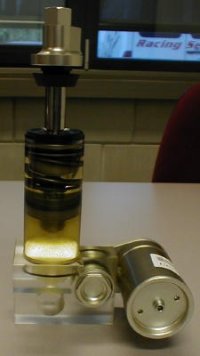
• Shock Body: The sealed unit that contains all the internal components.
• Shock Shaft: The rod that connects the swing arm (or suspension linkage) to the valving piston. The volume of the rod produces internal oil displacement as it enters the body.
• Shock Piston: The primary damping component of the shock. The piston seals to the shock body around its outside diameter and forces oil through its orifices and shims based on wheel movement. A shock piston and its shim stack are variable orifice mechanisms (as described below).
• Reservoir: A chamber connected to the main shock body by a fluid passage. The reservoir provides a holding space for fluid displaced by the volume of the shock shaft as the shock shaft travels into the body.
• Bladder or Reservoir Piston: The mechanism that seals the gas charge from the oil. The bladder serves to pressurize the whole system. The pressurized system forces the oil to travel through the shock piston, preventing cavitation.
• Shock Fluid: Hydraulic fluid typically consisting of synthetic oil stock with appropriate viscosity (flow properties) and thermal (heat resistance) properties.
• Seal Head: Creates a seal between the shock body and the shock shaft.
• Compression Adjuster: A small variable orifice device that limits the flow of fluid between the shock body and reservoir. The adjuster functions at a specific speed range, and with the implantation of a check valve offers no restriction in the rebound direction or shock shaft extension.
• Rebound Adjuster: An adjustable orifice using a needle and seat only. This adjuster serves as a bypass to the shock piston. On most current model off-road bikes, it bypasses in either direction; however, that is not always the case.
• Orifice: An orifice is an opening for fluid flow sized to restrict the flow of fluid depending on the speed of the fluid
• Variable orifice: A variable orifice changes its size based on the speed of the fluid. The piston shims and ports create a variable orifice and allows a shock to respond with more or less compression depending on shaft speed.
• Damping: Control of suspension motion by resistance of fluid flow through shock internal passages.
• Active (compression/rebound) damping: (Describes the nature of the fluid flow). The active description is used when referring to a swept volume of fluid. (The fluid stays fixed in position; the piston travels through the fluid).
• Passive (compression) damping: (Describes the nature of the fluid flow). The passive definition is used when referring to a displaced volume of fluid. (Displaced volumes are pushed across the valve mechanism and regulated).
• Cavitation: A pressure differential inside a shock that results in a vacuum in the opposite direction of piston movement. This vacuum causes the remaining fluid to vaporize. When the shock travels back the other direction it recondenses the vapor but results in reduced damping and hence very poor suspension performance.
To understand how a shock functions, it is easiest to look at the system in a series of cases.
• Case I: The shock starts as a pressurized system (with nitrogen). The bladder pressurizes the entire fluid body in the shock body.
• Case II: As the shock is compressed, the piston travels inside the shock body. The shock rod is now occupying increasing space inside the shock body. Since the system is closed, something must compress. The volume of oil occupied by the rod is displaced through the compression adjuster and compresses the bladder. Since the piston was in the shock body from the beginning, it displaces no additional fluid. Since the nitrogen is pressurizing the entire system equally, the fluid is swept through the piston, and the piston pushes no fluid into the reservoir. The volume of fluid passing through the piston ports is equal to the swept volume of the piston in the body MINUS the swept volume of the shock shaft. If the nitrogen were to leak or the shock was to be improperly charged, the pistons variable orifice might offer more resistance than the bladder. If this happens, the piston will push fluid into the reservoir, and the space behind he piston will not fill completely. When the shock begins its rebound stroke, the piston will have a distance of travel where no fluid is behind the piston. This section of travel will offer no resistance to the spring, and will obviously result in a miserable suspension action.
Although all this definition of components and their function may seem excessive, clarifying helps the rider to relate at a higher level, taking some of the mystery out of tuning.

